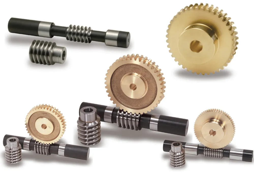
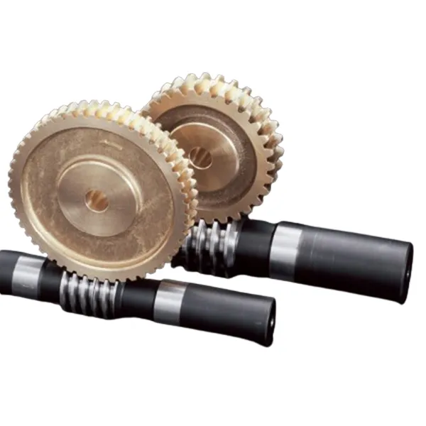
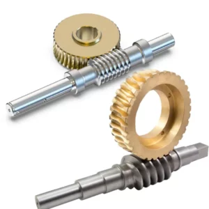
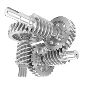
A Duplex Worm Gear is a specialized mechanical component designed for high-precision applications, offering enhanced durability and efficiency in power transmission systems. At FMP Company, we proudly manufacture a wide range of Duplex Worm Gears in various types and specifications to meet diverse industry needs. We also offer customized solutions tailored to your unique requirements. If you don’t find the specific model you’re looking for in our product list, it simply means we haven’t uploaded it yet—please feel free to email us with your desired specifications, and our skilled engineers will respond within 24 hours to assist you.
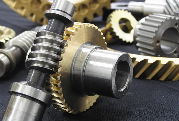
Specification of Duplex Worm Gear
A duplex or dual lead worm refers to a worm gear set where the two flanks are crafted with subtly distinct modules and diameter quotients, resulting in varying lead angles on each tooth profile. This design causes the tooth thickness to gradually increase along the worm’s length while the space between threads narrows, enabling precise backlash control.
On the worm wheel, these differing modules lead to unique addendum modification coefficients and rolling circle diameters on each flank, creating distinct profiles at the front and rear. However, the tooth thickness and gaps remain uniform around the wheel’s circumference.
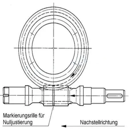
To adjust backlash, the worm is moved axially, aligning the section with the appropriate tooth thickness to engage the wheel, achieving the desired backlash level (see fig. 1). This method allows for straightforward backlash tuning to any preferred value during gear installation. Even worn gears can be finely and continuously adjusted without altering tooth contact or causing meshing issues.
In addition to the duplex approach described, other methods to regulate worm gear backlash include: adjusting the center distance by rotating an eccentric hub that supports the worm shaft and wheel; axially shifting a tapered worm (fig. 2a); splitting the worm into two parts (fig. 2b) that can be rotated or shifted relative to one another (Ott system); or dividing the wheel into two discs (fig. 2c) that can be adjusted closer together.
 |
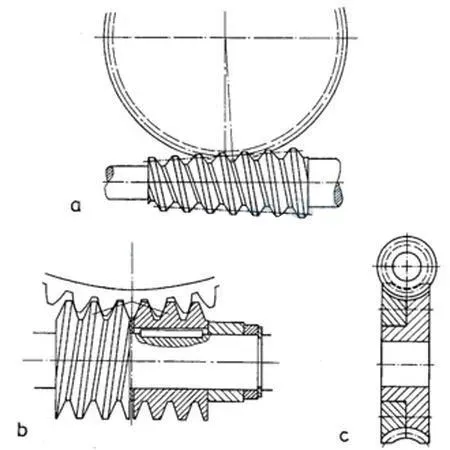 |
| fig 1 | fig 2 |
Assembly Caution Note
Duplex worm gears feature different modules on their right and left tooth surfaces, making proper alignment of the worm and worm wheel essential. Before assembly, please ensure the following two points are carefully checked.
- Confirming Assembly Orientation
Both the duplex worm and worm wheel are marked with an arrow indicating the correct assembly direction. During assembly, align the worm and worm wheel so that the arrow on the worm matches the direction of the arrow on the worm wheel, visible from the front. If the alignment is incorrect, the center distance “a” will exceed the standard measurement, leading to assembly challenges and poor gear meshing. (See Fig. 3)
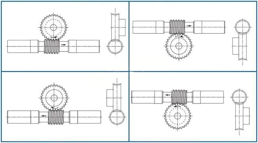
fig.3
Fig.3 Arrow mark indicates the correct orientation of two gears when assembled. As shown, the two arrows must point in the same direction.
2. Verifying the reference position
A V-groove (60 ゜, 0.3 mm deep line) on the tip peripheral of the duplex worm tooth marks the reference tooth. The gear set is designated to have a backlash of nearly zero ( ± 0.045) when the reference tooth is positioned in alignment with the center of rotation of the worm wheel with the center distance set at the value “a.” (Fig.4)
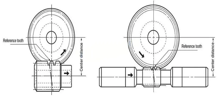
fig 4
Application Example

The above illustrations are only design examples and are not the designs of actual machines or equipment.
Related Product
This is only part of the products, please contact us for more products
